
Hydronic circuit purging: The basics
December 18, 2017 | By John Siegenthaler
 Nearly all closed loop hydronic heating and cooling systems are supposed to be filled with water, or a mixture of water and antifreeze. The only intentional air in the system is contained in the expansion tank.
The only exception to the above is a closed-loop, drainback solar thermal system where a volume of air is captured and managed within the system. That air is repeatedly used to replace water in the solar collectors when they drain at the end of each solar collection cycle.
Contrast the idea of a fluid-filled system with the fact that it begins its service life completely filled with air. Transitioning a newly-minted hydronic system, or an older system that has been drained, from air-filled to water-filled is called “purging.” The effectiveness of purging plays a major role in reliable and efficient system operation.
Nearly all modern hydronic systems rely on two methods to get air out and move water into the system. The first is called “forced fluid purging,” the second is “microbubble elimination.” Together these methods can get the system up and running quickly and ensure that it remains essentially air-free over its full service life.
THE OLD DAYS
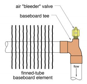
Figure 1
Getting air out of hydronic systems was not always straightforward. When I began working with these systems in the late 1970s, the common method of purging was to fill the system from the bottom up, counting on air to exit at multiple air vents, or at “bleeder” valves on heat emitters, or at other high points in the piping.
Imagine a scenario where several fin-tube baseboards each have a baseboard tee and a manually operated bleeder valve at the end of the fin-tube element. Figure 1 shows these fittings and how each is typically installed.
The installer opens all the bleeder valves before allowing water into the system. Pressurized water is introduced into the lower portion of the system by opening the “fast fill” lever on the system’s pressure reducing valve, or by opening a ball valve that bypasses the pressure reducing valve. Driven by the pressure of the building’s plumbing system, the water races through the piping, eventually gets to the open bleeder valves and sprays out tiny holes in the side of these valves.
Related: Keep heat produced by auxiliary boilers out of thermal storage
The trick is to catch those streams of water before they make a mess. That is pretty hard to do when the water is squirting out of four or five bleeder valves simultaneously at several locations in the building. If the hole in the bleeder valve faced outward, you could, in some cases, put a coffee can in front of each valve and hold it in place with a piece of wire. Still, this is a tedious approach to purging.
Even after the majority of the bulk air in the system is removed, the dissolved molecules of oxygen, nitrogen and other trace gases in the water take time to merge into bubbles that are large enough to be captured and ejected from the system by cast iron air scoops.
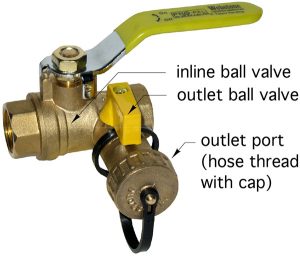
Figure 2
Older methods of purging that mostly relied on getting air out at the system’s high points were slow and inefficient.
Today, the hydronics industry has new hardware and methods that allow fast and efficient removal of air as the system is filled with water. One of the modern hardware devices that is now used routinely is the purge valve, an example of which is shown in Figure 2.
Purge valves combine two ball valves into a single body. One ball valve is inline with the piping being purged, the other is located in a side drain port that ends with a male hose thread and cap.
When used in a single circuit hydronic system, a purge valve should be installed as shown in Figure 3.
BULK AIR REMOVAL
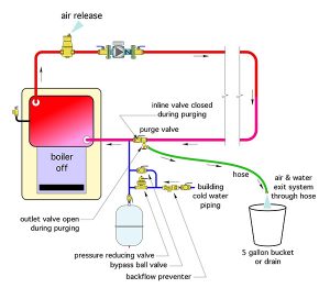
Figure 3
To fill and purge the circuit, close the inline ball on the purge valve, open the side port ball and connect a hose to the side port as shown in Figure 3. Open the fast fill lever on the system’s pressure reducing valve and if a bypass ball valve is installed as shown in Figure 3, open it.
Pressurized water from the building’s cold-water plumbing enters the system just downstream of the purge valve and flows through the circuit in a clockwise direction based on the layout in Figure 3. The closed inline ball in the purge valve prevents the water from “short circuiting” to the drain port.
The key to good purging is to create high water flow velocity through the circuit. I suggest a water velocity of at least four feet per second through the piping during purging. This allows the water to act like a liquid piston, pushing most of the air in the piping and components ahead of it and eventually back to the purge valve. The air then exits through the side port of the purge valve. Within a few seconds, the water stream follows the air out of the side port and through a hose leading to a capture bucket or drain. The system’s circulator can be turned on at this point to further increase flow velocity though the circuit.
Related: Step-by-step prep: Preparing condensing boilers for winter
Once the existing water stream is free of visible bubbles for several seconds, the side port of the purging valve is closed. The system pressure will immediately climb as building water pressure pushes more water into the system and compresses the diaphragm in the expansion tank. It is important to close the fast-fill bypass ball valve on the cold-water inlet piping within a second or two of closing the side port of the purging valve. If you do not, it is likely that the circuit pressure will exceed the rated pressure of the pressure relief valve, allowing water to be ejected from the latter. If this happens, crack open the side port of the purging valve until the system drops to the desired static pressure.
The process described will quickly remove most of the bulk air initially in the system. My experience has been that using this forced fluid purging approach eliminates the need to bleed air from high point vents. The fast moving water can force air through the system in any direction, including straight down, and eventually out of the purge valve.
FINAL SCRUB
The process of properly “deaerating” a hydronic system does not end with forced fluid purging. The cold water that now fills the system still contains between two and four per cent dissolved gas molecules, including oxygen, nitrogen and small amounts of other gases. You cannot see this molecular “air,” but it will come out to play once the water is heated. Well-designed systems stand ready to quickly capture it and eject it.
The system shown in Figure 3 also includes a microbubble air separator. This device contains a coalescing media that coaxes the dissolved gas molecules to form tiny microbubbles. The coalescing media also provides pathways for these microbubbles to rise above the active flow zone in the separator and merge together at the top. After a small volume of air collects in the upper portion of the separator it is ejected through a float-operated valve. The pressure within the system is what pushes the captured air out.
Microbubble air separators are a tremendous improvement over legacy cast-iron air scoops and, in my opinion, should be used in every modern hydronic system.
Coaxing dissolved gases out of the system fluid takes time, sometimes several days. The efficiency of dissolved gas removal is greatly improved if the system fluid is heated. Hot water (or hot antifreeze solutions) cannot retain as much dissolved gas as cool water and give up dissolved air more willingly as it passes through the air separator. Eventually the microbubble air separator, in cooperation with an automatic make-up water system, or an automatic fluid feeder, reduces the air content of the system to an insignificant level and keeps it there.
MULTIPLE ZONE SYSTEMS
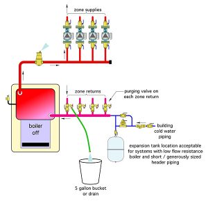
Figure 4
Most modern hydronic systems are not as simple as the one shown in Figure 3. These systems contain multiple zone circuits, or other parallel piping paths. The most efficient way to purge the systems is to install a purging valve on the return end of each circuit, as shown in Figure 4.
The purging procedure is very similar to that previously described. What is different is that each zone circuit is purged one at a time. Doing so produces the highest possible flow velocity through each circuit and the most efficient bulk air removal. When the purging valve on one zone return has a bubble-free return flow, close the inline ball on the purging valve and stop the cold water at the make-up water system.
Move the hose to the next purging valve and repeat the procedure. Keep doing this until each zone is purged. After water is forced into each zone, the zone circulator can also be turned on to further increase purging velocity. The microbubble air separator will do the final cleanup by capturing dissolved gases and ejecting them from the system.
P/S PURGING
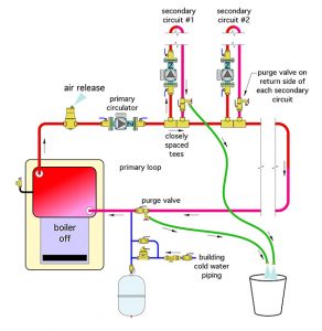
Figure 5
In the case of primary secondary systems I recommend using a purging valve on the return side of each secondary circuit as shown in Figure 5.
This approach eliminates the need for a ball valve between each set of closely spaced tees–the sole purpose of which is to force water through the secondary circuit during purging. The combination of the purging valve on the return side of the secondary circuit, along with isolation flanges on each secondary circulator, allows each secondary circuit to be completely isolated for service if necessary.
Start the purging procedure by isolating all secondary circuits, then purge the primary loop using the previously described procedure. Once the primary loop is purged, set up another hose and purge each secondary circuit individually.
PUMPED PURGING
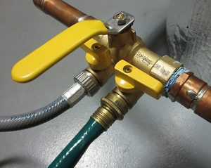
Figure 6
Some hydronics systems may not have access to pressurized cold water systems for purging. Other systems may need to be filled and purged with a premixed antifreeze solution. Both of these scenarios can be handled using a double port purging valve such as the one shown in Figure 6.
Double port purging valves combine two side port ball valves with a single inline ball valve. One side port allows fluid (water or antifreeze solution) into the system. The other lets air out of the system. A typical circuit using a double port purging valve is shown in Figure 7.
A submersible pump is used to force fluid in and around the circuit. Air exits the upstream side port of the purge valve. Eventually, a stream of fluid flows from the exit port and is carried back to the fluid reservoir. It is important to keep the end of the return hose under the fluid level in the reservoir to avoid creating bubbles that get pulled back into the purging pump. The purging pump is operated until the return stream is free of bubbles for several seconds. At that point, the outlet port of the purge valve is closed. This allows the purge pump to increase system pressure. Fluid is forced into the expansion tank until the system pressure reaches the maximum (no flow) pressure of the purge pump. The final step is to close the inlet port on the purge valve and turn off the purge pump. If additional pressure is needed in the circuit, more fluid can be added using a hand pump.
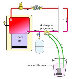
Figure 7
With modern hardware and methods it is possible to efficiently purge air from just about any hydronic system and keep that system essentially air free over its full service life.
John Siegenthaler, P.E., is a mechanical engineering graduate of Rensselaer Polytechnic Institute and a licensed professional engineer. He has over 34 years experience in designing modern hydronic heating systems. Siegenthaler’s latest book, Heating with Renewable Energy, was released recently (see www.hydronicpros.com for more information).

